
![]()
The front control arms are a bit of a weak spot on the otherwise durable Audi B5/C5 platform. The arms are made from aluminum, the ball joints tend to wear out relatively early. Here's how to change the upper front arms, as well as fit grease fittings to them, so you can get 'real' grease in the joint. The original fill grease has been found to be part of the problem, it's not up to the job. I like to inject synthetic grease into the joints. It's a good idea to spray the area around the 'pinch bolt' and the tie rod end with PB Blaster, or some other penetrant. These tend to rust in the upright very tightly. |
|
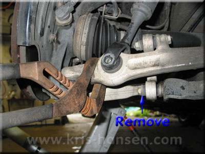
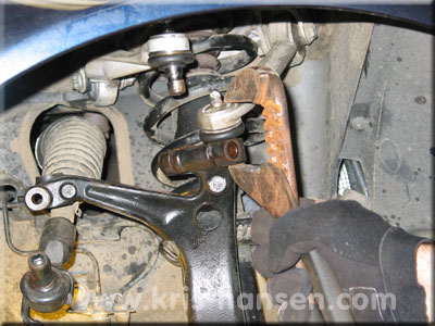
Step one is to SAFELY jack up the car, preferrably having both front wheels off the ground. This will make it easier to get the shock assembly removed. Loosen and remove the bolt for the sway bar link, and the lower shock bolt. To get the lower shock bolt out, use a large pair of slip joint pliers, or whatever you might have, and twist the lower front control arm towards the front of the car, to allow you to slide the bolt out. When you re-assemble, you can put this in backwards. Torque to 67 lb/ft. |
 |
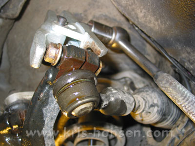
Step two is to get the pinch bolt out, so you can pull the assembly out. The technique I use is to drop the tie rod end, and use my impact gun to wiggle the pinch bolt free. To remove the tie rod end, loosen the 13mm bolt on the top, and the 16mm nut. I use my ball joint press to press the bolt out, and to press the tie rod end out of the knuckle. This is much easier than using your hammer to beat it out. Torque for the bolt on top is 4 lb/ft Torque for the nut is 37 lb/ft |
 |
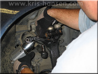
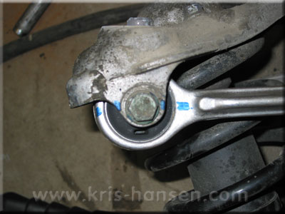
Now comes the fun part. You loosen the nut on the pinch bolt, soak the living heck out of it with your PB Blaster, give it a few taps with a hammer to help the PB work it's way into the hole, and then you have at it with your impact gun, and a u-joint. (well, I do it this way, I found it's the easiest way.) It takes a little work, but eventually it comes loose. It's best to replace this bolt. Use some anti Seize paste, and put it in backwards, to make it easier to take out next time.
Torque the nut on the pinch bolt to 30 lb/ft |
 |
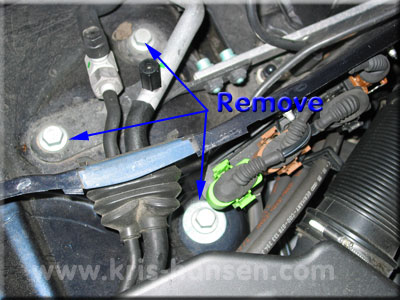
Now that you have the pinch bolt out, use a drift and a hammer to pop the control arms out of the knuckle. DO NOT use anything to pry the openings in the knuckle open. In the engine bay are 3 16mm bolts per side, which hold the upper mount plate in place. Thers is also a capture washer underneath, which is a colossal pain to get out. I used a screw driver, and just pried it out. Torque the bolts to 55 lb/ft |
 |
Once you get the upper mount bolts and the capture washer out, the shock and upper arms assembly should be free to come out of the car. Swing the lower shock mount over the lower front control arm, and remove the whole assembly from the car. Mark on the old arms it's positon relative to the mount plate. Then, line it up next to the new arm, and mark the new arm. This will help you install the new arm in the proper position. Note: According to the Bentley manual, you should set the gap on the control arms to be 57mm +/- 2mm at the outer edge. This picture shows where to make that measurement. Torque the nut to 36 lb/ft PLUS a 90 degree turn. |
 |
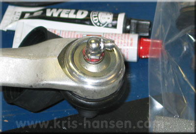
Now is as good a time as any to put grease fittings on your control arms. Drill and tap the steel disc on the control arm and using some washers as spacers, install the grease fitting. They don't have to be super tight, just enough to stay put. I have yet to lose one. I used to use vertical ones, now I use 90 degree ones. They are easier to get at once on the car. I use either Valvoline or Mobil1 synthetic grease. Dont' put too much in, or you will blow the boot off. |
 |
Assembly is pretty much the reverse, one tip is to use your big pliers from earlier to help get the ball joint studs in the knuckle. This makes it much easier than trying to do it just by hand. Please consult your manual for tightening torques, it varies from model to model for some reason. Also, when you tighten the lower shock mount and the sway bar link, do it with the car's weight resting on the suspension. This is to prevent the bushings from being twisted farther than they physcally are able to. |
 |